Arc welding has changed dramatically over the last decade. These advancements, along with the ability for power sources to connect to external devices has prompted robot manufacturers to refine robotic welding tools. From a robotics standpoint, this has inspired Yaskawa to develop a new Universal Weldcom Interface (UWI) that provides a common interface while presenting information using a specific power source manufacturer’s terminology.
The Need for UWI
While welding is performed around the world, there are regional differences in how it is approached. For example, in Asia, a robot is integrated with weld settings being a part of the robot program. With this method, amperage is generally set as a key variable for welding, while the power source has a database to determine the actual wire feed speed setting for a certain wire and gas combination. Similarly, North America tends to use the robot controller to store weld settings in the robot program as well.
Conversely, in Europe, operators store weld settings in power source files, referencing them when the arc is started. This approach keeps the robot motion and weld settings in different locations. While this is often beneficial from a control or security standpoint, it can also prevent the use of some robot capability to change or slope weld settings over a distance while moving along a weld seam.
These differences, along with varying shield gas usage, sophisticated power source technology, new processes with unique variables and customer preferences for accessing information have prompted Yaskawa to create a UWI compatible with Miller® Auto-Continuum™, Lincoln PowerWave®, SKS LSQ, or OTC Welbee digital power sources. The UWI expands on the advanced capability that is available in the standard Weldcom interface that is used to control Fronius TPSi or Yaskawa MotoWeld power sources.
What to Know about UWI
A power source will either accept weld settings sent from the robot or be designed to store the weld settings in files inside the power source. Keep in mind, that a modern-day interface needs to be flexible to utilize a variety of weld settings with different names and units.
Welding Process Selection
Processes are defined and control parameters are set in a laboratory. This is often done with instrumentation and a high-speed camera to observe arc phenomenon and set control waveforms to the ideal conditions. These are for a specific wire type, size and gas mixture, and they usually reside in the power source as a library that users reference to set up for their plant conditions.
The Universal Weld Interface has a process selection table where the specific processes for a plant can be registered from the power source. This is important because the processes may have different control variables, even from the same manufacturer. The selection table provides filters, so a specific wire type and size can be designated, and it allows the user to see all the processes available for selection in the power source. As an example, a job shop can set up different material combinations in the process table to be referenced by arc instructions.
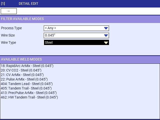 Figure 1 – Process selection filtered for 0.045 dia. steel wire (Lincoln PowerWave® library shown).
An interface should also be flexible enough to accommodate new process variations as they are made available. This might occur by updating power source software with a new library or adding a custom waveform developed by the manufacturer.
Weld Process Variables vs. AWS Essential Variables
Whether a weld is being made manually or with a robot, a Weld Procedure Specification (WPS) should be followed. AWS/ANSI B2.1 Specification for Welding Procedure and Performance Qualification outlines the essential electrical characteristic variables as Heat Input (J/in) = (Volts x Amps x 60)/ Travel Speed (in/min). This is based on the output of the power source, and few power source manufacturers use variables directly related to the output. Key process parameters may include wire feed speed, arc voltage/arc length, weld files/JOB Mode, travel speed and other weld settings for advanced processes.
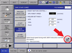
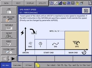
Figure 2a – UWI instructions use manufacturer names, units and ranges for weld settings.
Programming Weld settings in a Robotic Procedure
Many plants may not have a written WPS, but robots are programmed to apply the same parameters consistently. The robot program determines torch angles and travel speed, which are part of a WPS essential variables. Robot controls generally have the ability to store weld settings as global weld files or in weld instructions local to the specific program.
Arc files are set up for specific joint conditions, with amperage and arc length settings to “burn” the wire with minimal spatter for a range of travel speeds. The travel speed can be changed to determine the weld size. Arc files often allow for more detailed settings such as parameters to start the arc and build a weld puddle before traveling for larger welds. Arc end files may have secondary settings to fill the crater and burnback the wire. As global weld settings, arc files can be reused in different weld locations and programs where the WPS would apply. Changes to a global arc file may affect multiple weld locations and programs that have been saved and reloaded.
Weld instructions with local settings in the program allow a programmer to see the specific details for that weld location. This may lead to inconsistent settings applied across the part as a technician may “tweak” them. It may also be advantageous for a problem location that varies in fit-up and does require frequent adjustment of settings without altering more universal weld file settings. Some companies may prefer the in-line setting of instructions because it provides documentation of the weld settings right in the robot program and is not affected when programs are saved and reloaded.
Big News for Motoman® Robot Users
The Universal Weld Interface was designed to allow the flexibility to display process specific weld settings whether arc files or in-line instructions are used for weld settings. The weld settings are displayed with “tags” that reference the manufacturer’s nomenclature for that setting. Previous generation controllers were hard coded with the INFORM ARCON instruction only capable of displaying A(mps) or V(olts) as the units in a JOB. This limited the ability to use this instruction if the power source utilized different units or settings.
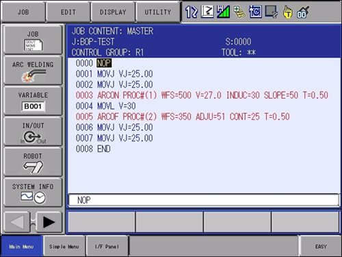 Figure 2b – UWI In-Line INFORM instructions use manufacturer names, units and ranges for weld settings (ARCON: Miller® MIG process, ARCOFF: Miller Accupulse™ process).
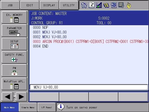 Figure 2c – UWI In-Line INFORM instructions even support use of variables for weld settings.
A new Dual Pulse feature is available with the UWI. Arc Start Files specify the welding process and the weld settings associated with that process. Dual Pulse allows a secondary Arc File to be specified and timers to specify duration in Primary and Alternate weld files. This creates a flexible way to define the frequency (total time) and the balance (time 1/time 2) of pulsation between the two settings. The power source may support the process to be changed while welding. The Graphic Arc Monitor Display (Fig 2d) was made with the Miller Auto-Continuum alternating between Accupulse™ at the peak and RMD™ as the background to produce a steel bead with ripple cosmetics similar to a TIG weld.
Weld Procedure Documentation for Quality
Companies that produce safety critical welds do maintain WPS documentation and require welds be requalified if parameters are changed beyond WPS limits. The robot control has several features, which can aid the administration of a WPS. For example, by activating a security level, weld settings and program editing can be restricted to certain personnel. Or, data displays can be used to show the data necessary to document WPS. This may include torch angles for weld location, weld lengths, travel speed, and amperage and voltage feedback while welding. Other valuable features include remote displays, remote monitoring and arc monitoring.
 Figure 2d – Robot teach pendant graphic display of welder output (New Dual Pulse alternating processes shown).
Digital Communication – Simpler or Harder?
As power sources move to digital communication networks, the wiring is simplified, but some tools to troubleshoot the network are beneficial. A UWI utility allows users to search the network for a power source and assign the IP address of the located device to the robot. This is particularly useful when the workcell has multiple robots with multiple welders and different IP addresses.
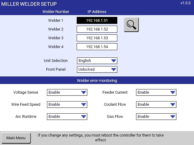 Figure 3 – Set-up utility simplifies network mapping (Miller® Auto-Continuum™ shown).
While the digital connection is monitored continuously to verify the health of the interface, what happens if the power source does not behave as expected? The UWI includes a logging function that records the digital traffic between the robot and the welder. It provides a downloadable file that users can email to Yaskawa Support Services to aid diagnosis.
This digital interface provides flexibility for different network platforms. Ethernet is common in North America while ProfiNet is popular in Europe. The UWI has a flexible interface module that can be edited by Yaskawa divisions around the World to adapt to the network or add new welders used in a specific region.
Take a Deeper Dive into UWI
As technology continues to advance, so will the control capability between the robot and power source. As a result, Yaskawa maintains close collaboration with power source manufacturers, allowing users to take full advantage of the capabilities available for a wide variety of applications and industries.
To take a deeper dive into the Universal Weld Interface, including weld process variables (i.e., wire feed speed, arc voltage, travel speed, etc.) and more on weld procedure documentation (i.e., remote displays, remote monitoring and arc monitoring), read our latest
article in
Welding Productivity.