Capable of vastly improving product throughput and part quality, robotic welding is optimizing manufacturing operations of all sizes around the world. High-performance welding robots provide fast, agile and reliable functionality to adapt to labor shortages, production inefficiencies, pressing market demands and more. However, the level of automation efficiency achieved typically relies on multiple factors beyond implementing an extremely flexible high-speed robotic arm.
As one of the leading automation efficiency factors, the thoughtful design of a robotic weld fixture should not be overlooked. A poor tool design and installation job – even when associated with a high-end robot – has the potential to be terribly inefficient and cost-prohibitive. The good news is our Yaskawa experts have proven tips, considerations and best practices to help company leaders make intelligent choices during the design and implementation stages that will bolster production and return on investment (ROI).
Primary functions of a robotic weld fixture
There’s more to robotic weld tooling than most people think. When selecting a robotic weld fixture, it’s important to first remember the tool’s primary functions:
-
Provide clear access to the weld joint with the proper torch angles.
-
Locate the weld joint to be within the process window. This is typically ± ½ the weld wire diameter for gas metal arc welding (GMAW) and is much tighter for gas tungsten arc welding (GTAW).
-
Clamp and provide highly repeatable locations for the parts to provide zero gaps in the weld joint.
-
Position the weldment in the fixture to:
-
Put the weld joints in the optimal position and minimize robot motion.
-
Provide the easiest load and unload orientation for the operator.
Note: keep in mind the preferred robotic welding position is flat or horizontal. On thin gage (<⅛”) vertical down should be considered based on the joint design and weld requirements. Also, breaking the weldment into sub-assemblies may be necessary.
Best practices for designing or selecting a robotic weld fixture
Once you grasp the concepts of the tool’s primary function, there are other considerations to apply to the tool design/selection process, such as:
-
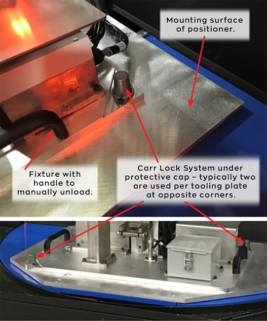
Note if the tool will be mounted to a positioner. If so, pay close attention to its specifications (such as overall span or weight that will likely be greater than that of just the part), and accommodate those when choosing a fixture.
-
Identify the weight and center of gravity of the tool with parts on the fixture.
-
Use counterweights for balance, if needed, but stay within the maximum load limits (for torque and inertia) for the positioner ratings.
-
Be certain the operator can keep up with the robot cycle; sometimes, multiple parts can be designed into the fixture to extend arc-on time for time matched loading/unloading of new parts.
-
Decide on manual vs. pneumatic clamps. Both are acceptable, but each can impact cycle time.
-
Clamp open, clamp closed, and part-in-position I/O signals should be used to communicate with the robot.
-
Protect against the elements, such as welding heat, UV light and spatter. This goes for surfaces, hoses, signal wires/cables and threads. Note: do not use Allen head screws.
-
Consider the impacts of distortion for welding a part. Pre-cambering or tightly clamping the parts before welding may help.
-
Be sure that the part can be removed after welding.
-
Be sure the part is a good fit for robotic automation. Sometimes, a part may need to be redesigned to accommodate the robot. Slot and tab construction is an ideal solution for many parts.
-
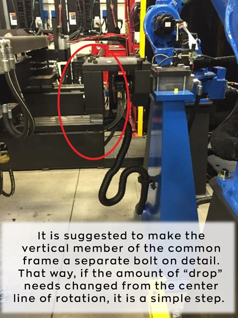
Properly locate the center of rotation, especially for use with two-axis (or more) positioners.
-
Use shims. A good range is around 3 mm.
-
Do not use magnets, as weld spatter sticks to them, causing arc blow.
-
Tooling and details should be durable, hardened and replaceable for greater longevity.
-
Check to see if the fixture needs to be at a different angle to ease the loading and unloading operation.
-
Consider the type of power clamps used and what happens to the fixture when an e-stop is applied.
Frame options that may be beneficial
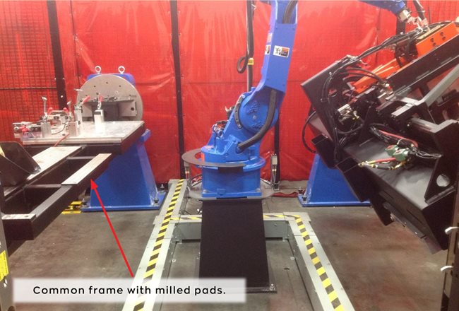
Use a
common frame (between headstock and tailstock) with milled pads for bolt on details or smaller modules.
-
Frame style: drop beam, single rail, full frame.
-
Frame design: modular, not one weldment for flexibility.
-
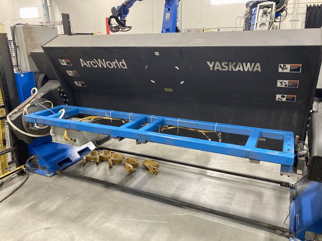
A common frame concept between a headstock and tailstock is known as a "picture frame", which provides dimension to fit your application.
-
A single beam concept, or an opening in the “picture frame”, is ideal for allowing access to 360-degree welds after inverting the frame.
Helpful products for optimizing weld tool functionality
The right mix of peripheral tools and upgraded products can help optimize an application. A few options manufacturers may want to consider using include:
-
AMPCOLOY® 940: this special thermally conductive alloy has high mechanical properties and is ideal for a heat sink to pull heat away from the parts being welded.
-
Carr Lock® System: this system is ideal for manually changing out fixture plates from a common frame or mount.
Simple steps to checking a new fixture design
To see if a tool design will put the weld joint in the same location regardless of the operator and part variations, it is suggested to implement this six-step process:
Note: steps 1 – 5 should use the same robot operator.
-
Load a set of parts.
-
Program the robot to point to the weld joint with the weld wire.
-
Get a good visual or photo of the position of the wire in the weld joint.
-
Remove the parts and reload the same parts. Drive the robot to the programmed point and check the weld wire position to the weld joint. Note: it should be the same as in step #3.
-
Repeat 1 through 4 using a different batch of parts.
-
Repeat 1 through 5 using a different operator.
Solid weld tool design for optimum productivity
A wealth of knowledge exists to guide decision makers on their robotic automation journey. While working with an experienced robot OEM or supplier is ideal, specific questions regarding tooling can always be addressed by modular component suppliers, like Rentapen or MISUMI, or from weld tooling manufacturers, such as Stryver Manufacturing or Automation IG. Regardless of how a robotic weld tool is brought to fruition, a good fixture design is critical to application success and optimum productivity for better ROI.
Josh Leath is a Senior Product Manager

Connect on: