Innovative improvements in the accuracy of vision technology, especially those related to robotic automation, have gained considerable traction in the last few years, reigniting interest for the utilization of
Vision Guided Robotics (VGR) throughout the manufacturing landscape. Application hurdles that were once viewed as impossible are now being met head on via a combination of affordable robots, intelligent sensors and high-tech imaging systems, bolstering the confidence in production facilities of all sizes to pursue the implementation of robotic solutions for high-volume demand.
Types of Vision Systems
Thanks to advancements in camera resolution, image processing speeds and integrated lighting for vision technology, today’s VGR tools offer great functionality for detecting various part shapes in unique production environments. The type of system required to complete a specific task, however, depends on certain criteria.
2D Vision
The most commonly used method of machine vision, 2D systems provide X, Y, Rz angle coordinates for the location of an object. Occurring in a single plane, where part depth data is not required, this form uses grayscale or color imaging to create a two-dimensional map, revealing part differences. No Z or tilt (Rx, Ry) information is provided, and working distance remains constant.
3D Vision
Often providing game-changing benefits to manufacturers, 3D vision utilizes an extra dimension to provide X, Y, Z, Rx, Ry and Rz angle coordinates of an object. With vision data occurring in different planes, 3D imaging utilizes height measurement to learn about an object, enabling the robot to efficiently recognize, pick and place it as programmed.
3D Vision Solutions
While 2D vision capabilities have grown, the method still requires traditional lighting sources and the presence of contrast and color. Parts must also be positioned or stacked in an organized, predictable pattern, so they can be easily imaged and picked. For these reasons, VGR technology for three-dimensional bin picking has undergone substantial improvements to eliminate the need for pre-arrangement of parts prior to being located and moved by the robot, making 3D vision a viable asset for many applications today.
Innovative and easy-to-use piece picking hardware/software soutions equipped with a single 3D camera inside the unit, like Yaskawa’s
MotoSight™ 3D BinPick, give robots the ability to work in virtually any manufacturing setting. Implementing technology of this nature is quite helpful for manufacturers because there is no programming at the system level, as the solution automatically matches a pre-loaded 3D CAD model to any part, enabling the robot to move randomly placed parts to the preferred program point. This has made 3D vision solutions ideal for multiple production environments where:
Parts are positioned in a bin in various ways – facilitating a wider selection of applications, 3D bin picking allows parts to be positioned in a container with some organization and predictability, or it can allow parts to be scattered in random positions (including different orientations) within a bin. MotoSight 3D BinPick easily accommodates complex imaging and picking tasks.
Parts are currently picked manually – traditional bin picking tasks done via humans or other non-intelligent devices have opened the door for flexible, high-speed order fulfillment approaches for various reasons. Increased worker safety, lower production costs and optimized product throughput are just a few benefits that are prompting more and more manufacturers to utilize this technology.
Parts must be picked and properly oriented – 3D vision systems are now designed in such a way that shapes can be recognized as never before. They easily maneuver the robot to random parts in the middle or on the edge of a container, before expertly picking and placing them for the next machining step or assembly phase in the production process.
MotoSight 3D BinPick Process
High-tech imaging solutions like this provide manufacturers with an accurate, streamlined process that simultaneously identifies and picks randomly placed parts. The process entails:
1) Image capture – a high-quality camera with integrated lighting takes a photo of the part.
2) Quick discovery – the visual guidance provided by the solution mimics the human visual process, identifying the part to be picked.
3) Precise CAD fitting – the solution automatically matches a pre-loaded 3D CAD model (up to 200 models are supported) to the part, providing simplified and accurate part registration by the robot. The location and orientation data is automatically transferred to the robot controller via Ethernet.
4) Grasp priority –a unique algorithm allows the system to determine the best grip location of the part to be picked while avoiding collisions with other parts in the bin as well as the bin itself.
Benefits of 3D BinPick
Trusted by many major OEMs and Tier-1 part suppliers, 3D bin picking solutions have been proven to work for a wide variety of industries. From automotive to everything in between, various products in a multitude of shapes, sizes and materials can be recognized and picked with this technology, offering the following benefits:
1) High speed recognition – MotoSight 3D BinPick equipped with the Canon
® RV300 or RV500 offers extremely fast recognition time at 1.8 seconds. Optional software may improve time.
2) Dynamic picking strategies – multiple pick points can be taught completely through the software. Collision avoidance technology is also used.
3) High precision and repeatability – precise CAD model fitting provides application accuracy, where repeatability of 0.1 mm can be achieved via the Canon RV300.
4) Single measurement – with this system 3D position and orientation of a part is detected in a single step, and additional 2D scanning is not required. This is advantageous because many 3D vision solutions use a two-step recognition process, which is more time consuming.
Resurgence for Vision-Guided Robotics
To aid in the production value chain for the manufacturing of parts and the packaging of goods, greater emphasis is being placed on flexible 3D bin picking solutions. Thanks to Grant Zahorsky, 3D Machine Vision Engineer at
Canon USA, here are some examples of successful 3D bin picking tasks:
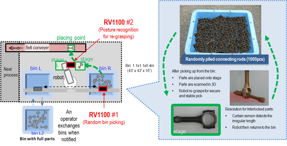
1) Connecting Rods – in order to reduce downtime caused by replacing a bin, the “slider mounting option” is used. This allows the robot to automatically continue picking parts from the second bin when the first bin is empty. Due to the part shape, material used and the possibility of parts interlocking with each other, the part could occasionally slightly slip from the grippers. To avoid this situation, the parts are placed on a stage, rescanned with the Canon 3D sensor, and then, finally regrasped. If multiple tangled parts are picked, a curtain sensor detects the irregular length of the parts and the robot returns the parts to the bin.
 2) Gear Feeding
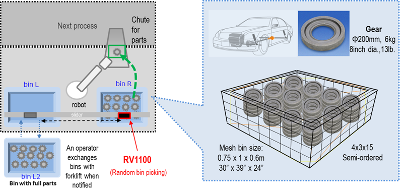
 – using the flexibility of the Canon 3D recognition software, a mesh bin with semi-structured parts were registered in the software, so that the robot could accurately pick the parts from the bin while avoiding collisions in or around the bin. In order to reduce down time caused by replacing a bin, the “slider mounting option” is used. This allows the robot to automatically continue picking parts from the second bin when the first bin is empty.
 3) Rubber Parts
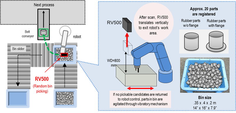
 – if no pickable candidates can be found, a shaker is used to stir the parts, so that the Canon 3D sensor can rescan the bin. A vertical slider is also used to slide the RV500 out of the robot’s work area, so that the robot could reach any location within the bin while avoiding any possible collision. A custom end effector consisting of both suction cups and a mechanical gripper was created in order to completely empty the bin.
 4) Crank Shaft
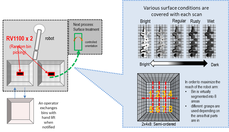
 – by using two Canon 3D sensors, the downtime of the system is minimized. In order to maximize the reach of the robot arm, the bin is virtually segmented into eight areas. Different grasps are used depending on which the area the detected part is located. The various surface conditions of these crank shafts are able to be detected automatically with the Canon 3D recognition software without manual intervention between each scan.
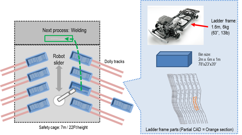
 5) Ladder Frame
 – as these large parts (L: 1.6m) extend beyond the measurement area of the RV1100, the “partial CAD recognition option” is used to accurately detect and pick the parts from the bins. In order to locate the parts from various, different bins, the “slider mounting option” is used.
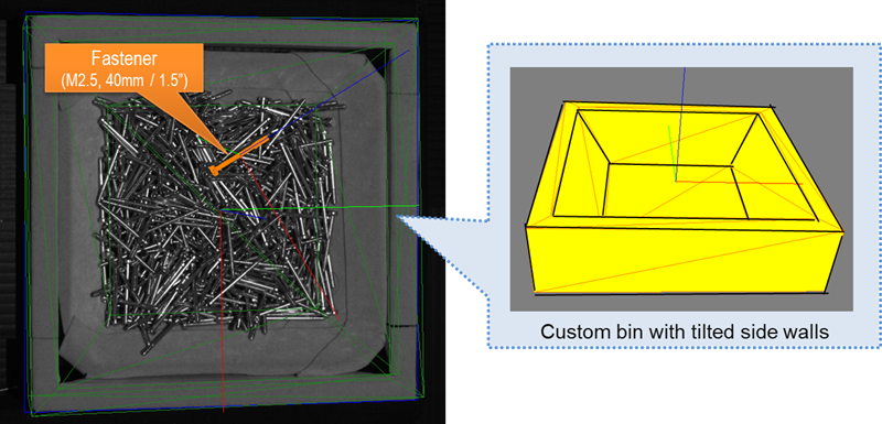
 6) Fastener
 – by using a custom bin with tilted side walls, the parts in the bin gather toward the center of the bin. This strategy further eliminates any potential collisions between the end effector and bin walls.
Conclusion
While the above examples are far from all-inclusive, they show how far the field of vision-guided robotics has come. For more about MotoSight 3D BinPick or to learn about best practices that must be applied to implement a vision solution, contact our collaborative team of experts today.